
 |
| Say hello to my bulky little friend. |
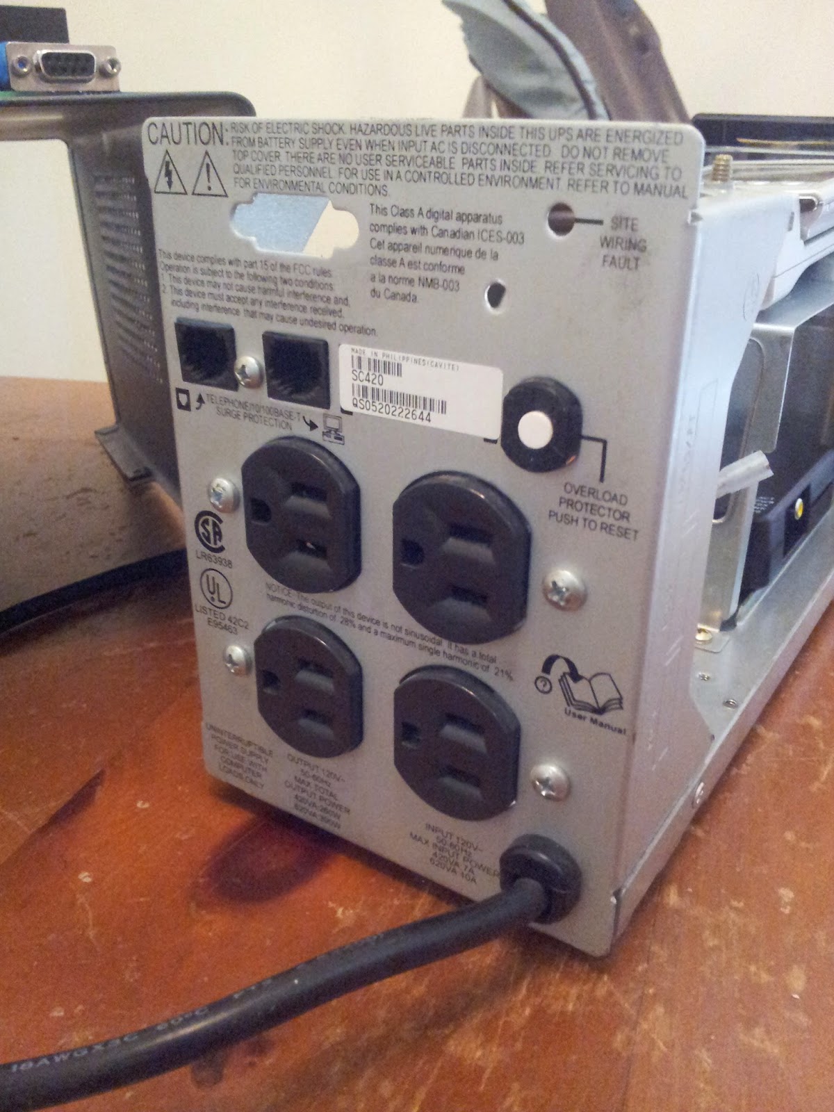
As part of the Back to the Hack series and related to my hidden war dialer project I decided to see if there was a better option to hide my war dialer, Arduino, or Raspberry Pi. In my previous post I said I would use a gutted APC-350 UPS. A trip to SkyCraft and $15 dollars later I found myself with a APC-420. I love how it's well worn, scratched, and has little dents. The device will look like its been tucked away at a target facility for years. It will be a much roomier home for all my hack-a-tronics and will blend into any cube farm, IDF, or MDF perfectly.
After the jump see the tear down and some of my first thoughts heading into the hidden war dialer build.
Doctor, we are going to need to AMPutate.
The device I purchased was already sans battery which for my use was perfect. I just need a power strip with a place to hide things. There are boards, transformers, and all manner of other stuff that must be removed. Let's get to gut'in.


 I may cut it up and then solder wires between the pins. I may get fancy and have a new board custom printed. I'm not sure yet.

 Here is one of the first problems: the removed main board has the serial port attached. To make this a clean build the serial port hole needs to be filled. Leaving the hole would definitely raise suspicions.
 The front bezel leaves an excellent area to hide antennas for WiFi or cellular connections to be included in future builds. Placing any antennas outside the metal box, but covered by the plastic bezel, should work very well.
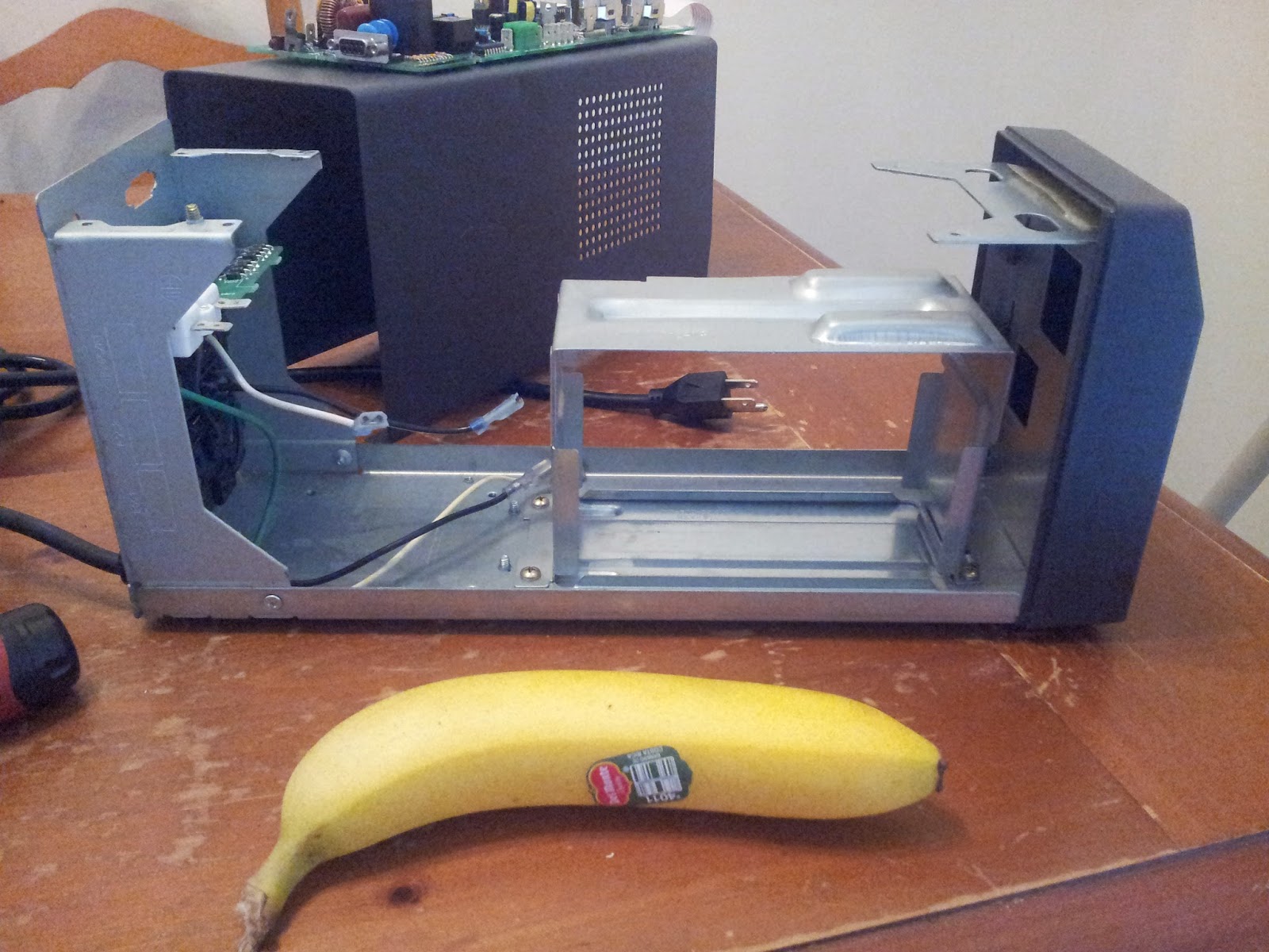 Gutted and ready to start building! The main concern here will be weight. The device is now very light. Metal plates will need to be added. If someone were to pick up the device after deployment the lack of weight may cause question.
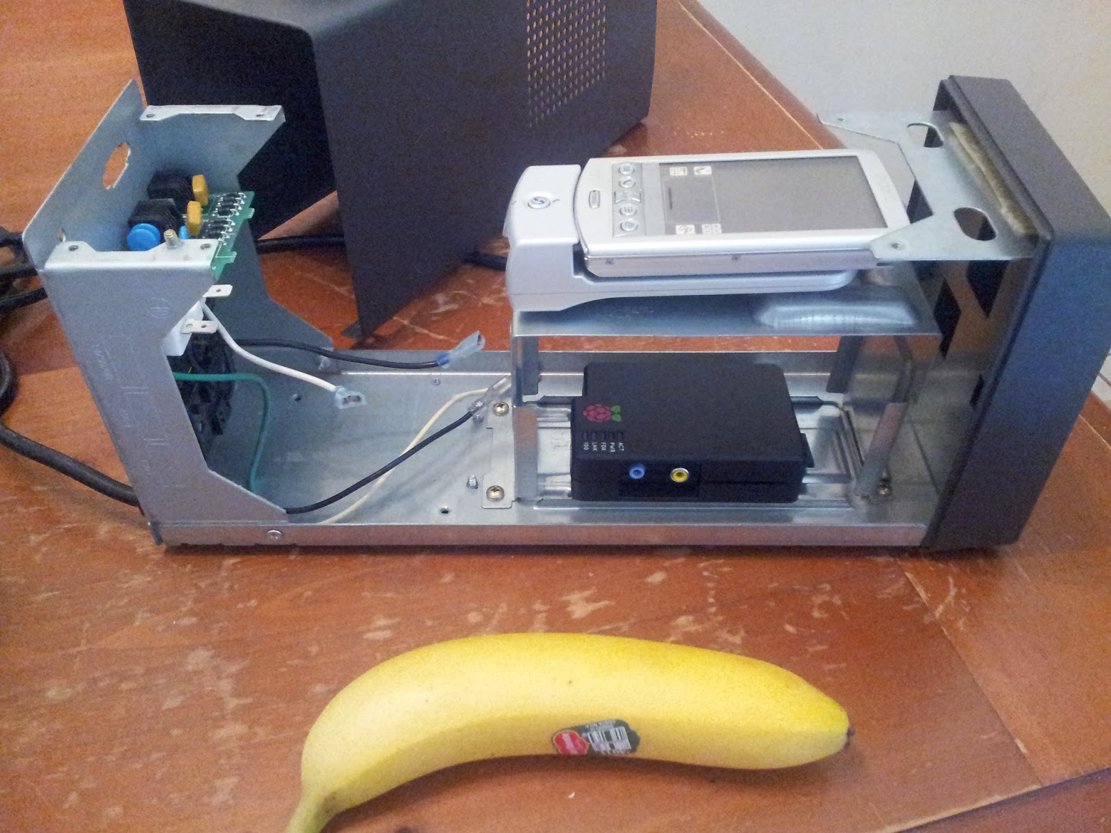 More than enough room for the war dialer or a Raspberry Pi or both!
 THERE'S SO MUCH ROOM FOR ACTIVITIES!
Next steps:
- Wire a third internal power outlet.
- Fabricate either 3D printed mounts for hardware or hand build them.
- LED light to fake normal operation of the unit.
- Modify RJ-11/RJ-45 bypass for war dialer or Raspberry Pi.
- Adjust for the weight of the missing transformer and battery.
- Fill in serial hole with a DB-9 serial port.
No comments:
Post a Comment